In this
article:
The Solution
Navigation:
ParentHome
Hardware
Software
Techniques
Controllers
Reviews
Index
Introduction
Counting in HEX was easy, counting in decimal is a bit trickier. Plus we’ve got a new gizmo to play with, an 8 digit multiplexed LED display.
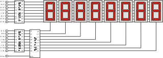
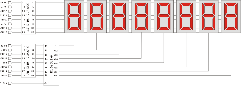
The schematic below is the display I built for this project (click here for a larger view). The display multiplexes 8 seven segment displays on one set of display driver lines.
When the display is rapidly scanned using the FPGA it appears to your eye as if all of the digits are lit simultaneously. Further, it saves FPGA resources since you only consume 16 I/O lines (same as the BEDLED board) but get eight digits to play with.
Like a good developer I’m reusing all of the previous projects in this one, that’s right the looper too. But it turns out it may not be the best solution.
Of course things never turn out as you would expect, otherwise you wouldn’t really be learning anything now would you? One of the twists in this project was that I designed the multi-digit board and then wrote the VHDL code to drive it. When I first tried it out the displays were way too dim (you couldn’t read them with the lights on!). As it turns out I had failed to consider the voltage dropping potential of the green LEDs and the NPN current sinks in my current limiting resistor calculation. So I had 180 ohm resistors and was just barely turning on the LEDs! I measured the voltage (about .6 volts across them) and came up with the 47 ohm values. This made the display much brighter (nearly acceptable actually.) However, it is plenty bright when showing 1, 2, even 4 digits, but gets less bright showing 8. This is due to the ‘duty cycle’ effect of only turning on the LED for 1/8th of the total refresh time. If I redesign the board I’ll use the additional 2 I/Os that are available on the plug on connector and make it a dual 4 digit display. That way I need only mux 4 digits at a time and the display would be fine.
I also got to learn about about how precedence affects things in VHDL designs. In particular, the ‘TEST’ input pin was lower precedence than the ‘BLANK’ pin, thus when blanking leading zeros my initial design would only light up in test mode those digits that had non-zero contents. That was fixable in the HEX_DISPLAY module.
Leading zero suppression and decimal support were also both interesting. This design hard codes the decimal point between digits 7 and 8. Then the leading zero suppression code in COUNTER makes sure it will neve suppress the last two digits. However, it should be possible to do this in the MUXDISP module and have it work automatically so that leading zero suppression only occurs on the digit to the immediate left of the decimal point.
I did get a great display out of this project and I’m looking forward to using it on the next one, the mouse port. As I actually assembled two 8 digit displays I should be able to have the X and Y co-ordinates of the mouse display in real time on the two displays. Hmmm, maybe I’ll have to support negative numbers after all.
The Project
Design a 32 bit ( 8 decimal digits!) counter that displays its count on
an eight digit, multiplexed
LED display. The counter
should count at a rate of 10 counts/second and display a decimal
point between digits 7 and 8. Use the CLOCK_10HZ and HEX_DISPLAY entities
in this project. Include the ability to optionally blank leading zeros
on the display. The pin-out for this chip is as follows:
| Pin | Direction | Description |
|---|---|---|
| SRC_CLK | IN | This is a 24Mhz input clock. |
| SEGS[6..0] | OUT | These lines connect to the common 'segment' lines of the multiplexed LED display. |
| DIGITS[7..0] | OUT | These lines connect to the common 'enable' lines of the multiplexed LED display. |
| BLANK | IN | When asserted "high" this pin enables leading zero suppression on the display. |
| RST | IN | When this pin is asserted "low" the counter resets to 0. |
| TEST | IN | When this pin is asserted "high" all of the LEDs in the display light up. |
| DP | OUT | This signal connects to the common "decimal point" input of the multiplexed displays. |
This project is most easily accomplished by breaking it up into a number of sub components that are each testable on their own. You will be re-using parts from the other projects so that will aid your implementation.
Purpose
This project is actually useful. Back in the day one could sell a chip with these capabilities to a company that was building a frequency counter. In that scenario a frequency would be gated on to the ‘src_clk’ pin for a fix amount of time (say 1/10th of a second) and the resulting count would be displayed as the frequency.
Discussion
If you will recall the hex counter from the previous project this one seems similar at first, however there is an annoying problem: How does one count by tens?
Thus this project actually becomes two projects, the decimal counter half and the multiplexed digit display half. Both bring some interesting challenges into the mix.
The SRC_CLK input is again 24Mhz so the CLOCK_10Hz component can be used to turn that into a 10 hz counting clock, however you will need to feed it directly into the multiplexing display component so that the display can be scanned at least 100hz.
Leading zero suppression had me stuck for a moment until I realized that each digit “knows” when it is zero. Use that knowledge to implement supressing leading zeros, remember that the least significant digit is never suppressed (even when it is zero.)
Going Further
This circuit was a chip sold by National Semiconductor and others and used in a variety of multi-meters, frequency counters, etc. There are lots of interesting things you can do with it. Some other ideas:
- Convert this counter to a frequency counter by adding in a gate/reset pin..
- Do minute and hour roll-overs (turning it into a timer rather than straight seconds counter)
- Support negative counts with a floating “minus” sign.
- Set it up for counting 100ths of a second and then make a reaction speed timer by turning on an LED and waiting for the resulting button press by the user.
The Solution
The code I ended writing for this is here which includes links to two sub-components of interest:
- Digit Display Multiplexer - Digit display control
- Decimal Counter - Decimal (as opposed to binary) counter.