In this
article:
Source Code
License
Navigation:
HomeHardware
Software
Techniques
Controllers
Reviews
Index
Description
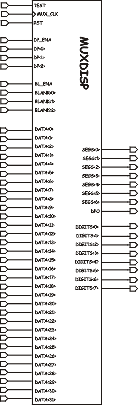
On the right is the schematic symbol for the MUXDISP module. It has 43 inputs and 16 outputs. It is actually the “meat” of the multi-digit counter solution and while it works fine I’m not sure its the best way to implement it yet.
There are several sections in the source code below that were interesting to write. The first is the blanking code.
The blanking code controls the signal cur_blank and asserts it high when the current digit being displayed is less than the number of digits to be blanked. It is also gated by the BL_ENA which, as its name implies, enables the blanking to occur.
The decimal point code is next, with the same logic as the blanking code, except that it only enables the decimal point when the requested digit equals the current digit. Further, when the DPO pin is assigned later in the code, it comes on when either the decimal point is to be displayed or the test pin is being asserted.
After the decimal point code there is a process that generates the display. This process is clocked by MUX_CLK and it causes the cur_digit signal lines to get incremented. One of the things I learned here was that once the LEDs were scanning above 100hz they were all on and so scanning them at exactly 100hz wasn’t necessary. Thus, to reduce the complexity of this chip (and hence its gate count) I changed the loop test to just watch when the loop count rolled over to zero and then to up the current digit. I expect an even cheaper solution would be to increment on the rising edge of the top most bit in this counter.
Finally, the module muxes out the data pins to the displays, and turns on one display enable for each digit. These are both driven by the cur_digit signals but I’ve not yet learned if I can do these at the same time with one set of statements or if I’m forced to use two statements as I have done here.
The Source Code
-- MUXDISP.VHD                    Chuck McManis 19-Mar-2001
--
-- This then is some VHDL to drive 8 digits of display with only 16 lines on the
-- FPGA. Our circuit consists of 8 lines going to all 8 of the seven segment
-- displays, and then 8 lines going to a Toshiba darlington current sink that
-- "enables" each digit by grounding the common cathode pin for that digit.
-- If you turn on more than one, you get more than one digit lit. Fun yes?
-- Just don't over draw the current on the FPGA!
--
library IEEE;
use IEEE.STD_LOGIC_1164.ALL;
use IEEE.STD_LOGIC_ARITH.ALL;
use IEEE.STD_LOGIC_UNSIGNED.ALL;

entity MUXDISP is
    Port (
        mux_clk : in std_logic;                -- Multiplexing clock for display
        rst     : in std_logic;                        -- Reset pin
        data    : in std_logic_vector(31 downto 0);    -- Eight 4 bit digits.
        bl_ena    : in std_logic;                        -- Blanking enable.
        blank   : in std_logic_vector(2 downto 0);    -- Which digits
        dp_ena    : in std_logic;                        -- Decimal point enable.
        dp      : in std_logic_vector(2 downto 0);    -- which DP to light
        test   : in std_logic;                        -- Test Enable
        display : out std_logic_vector(6 downto 0);    -- Segment output
        dpo     : out std_logic;                    -- decimal point output.
        digits  : out std_logic_vector(7 downto 0)  -- digit selectors
    );
end MUXDISP;

architecture behavioral of MUXDISP is

    -- I use the previously defined hex_display component as the means
    -- to drive the segment pins.
    COMPONENT hex_display
    PORT(
        test : IN std_logic;
        blank : IN std_logic;
        data : IN std_logic_vector(3 downto 0);
        segs : OUT std_logic_vector(6 downto 0)
    );
    END COMPONENT;

    signal cur_digit : std_logic_vector (2 downto 0);
    signal digit_data : std_logic_vector (3 downto 0);
    signal cur_blank, cur_test, cur_dp : std_logic;

begin
    -- Map a HEX display decoder connected to the digit_data pins
    -- and driving the segment output on the chip.
    u1: hex_display PORT MAP( test => test, blank => cur_blank,
                              data => digit_data, segs => display);

    -- The chip handles leading digit blanking by asserting blank
    -- when ever the value of blank is less than the current digit.
    -- This means you can never blank digit 8
    cur_blank <= '0' when (bl_ena = '0') or (test = '1') else
                 '1' when blank > cur_digit else
                 '0';

    -- The current decimal point deal is handled a bit
    -- differently since it only lights at one place.
    cur_dp <= '0' when dp_ena = '0' else
              '1' when dp = cur_digit else
              '0';

    -- Now connect the DP output pin which is either
    -- on because we're testing the LEDs or on because
    -- this is the current decimal point digit.
    dpo <= '1' when test = '1' else
           cur_dp;


    -- Generate what appears to be the continuous display of 8 digits
    -- by lighting each digit up in sequence. If you can get all 8
    -- digits on at least once every 100 milleseconds, then they will
    -- look continuous. Just don't pick a multiple of 60hz!
    -- On the SPARTAN2 board 'mux_clk' is 24Mhz
    gen_display: process (rst, mux_clk) is
    variable d_clk : unsigned(13 downto 0);
    begin
        if (rst = '0') then
            cur_digit <= "000";
            d_clk := "00000000000000";
        elsif rising_edge(mux_clk) then
            -- each time the count "rolls over" switch to the next
            -- digit. With 14 bits that is a count of 16384 and a
            -- freq of 1.465Khz, divided by 8 means each digit is
            -- illuminated 183 times/sec. (plenty fast)
            if (d_clk = 0) then
                -- select the next digit to display
                cur_digit <= cur_digit + 1;
            end if;
            d_clk := d_clk + 1; -- now keep counting up
        end if;
    end process;

    -- This statement muxes out the data pins to the hex decoder
    -- based on the cur_digit value. Digit 0 is the MSD and
    -- digit 7 is the LSD.
    digit_data <= data(31 downto 28) when cur_digit = "000" else
                  data(27 downto 24) when cur_digit = "001" else
                  data(23 downto 20) when cur_digit = "010" else
                  data(19 downto 16) when cur_digit = "011" else
                  data(15 downto 12) when cur_digit = "100" else
                  data(11 downto  8) when cur_digit = "101" else
                  data( 7 downto  4) when cur_digit = "110" else
                  data( 3 downto  0);

    -- This statement drives the "digit enabled" line based on
    -- the current digit. Now it looks like its backwards but
    -- it isn't, since the digits are 7 downto 0, digits<0> is
    -- on the right hand side, so cur_digit = "000" enables
    -- digits "00000001" etc.
    --
    digits <= "00000001" when cur_digit = "000" else
              "00000010" when cur_digit = "001" else
              "00000100" when cur_digit = "010" else
              "00001000" when cur_digit = "011" else
              "00010000" when cur_digit = "100" else
              "00100000" when cur_digit = "101" else
              "01000000" when cur_digit = "110" else
              "10000000";

end behavioral;
License

This work is licensed under a Creative Commons Attribution-NonCommercial 3.0 Unported License. You are free to play around with it and modify it but you are not licensed to use it for commercial purposes. Click the link above for more details on your rights under this license.