In this
article:
The Microchip MPLAB-ICD in circuit debugger
Summary
Fixing the LAB-X3
Further Notes
Navigation:
HomeHardware
Software
Techniques
Controllers
Reviews
Index
Introduction
PICs, those single chip MCUs from Microchip, are cool. They just are, but perhaps what is even cooler is that Microchip has an extremely enlightened view about what there job is. Yes, their job is to make cool chips, and its our job to design them into cool projects. Because Microchip understands this, their development tools are free. Which means that you and I, dreamers, inventors, and engineers, can “test the water” with nearly zero dollars invested. Further, there is a robust cottage industry around building programmers, prototype boards, etc.
The last time I did any serious PIC work the 16C54 was current, the 16F84 was new, and the best way to program them was with a dedicated programmer like the Needham EMP–20. Since that time, Microchip as gotten into “Flash” chips in a big way and this makes using these things not only fun, but reusable too!
As Needhams winds down support for the EMP–20 (go ahead call them, its true) they admitted that no, they weren’t going to update their DOS software to program the 16F628 (but if I bought their new EMP–30 it was going to be able to program the ’628 and its program ran under Windows!) Well looking around showed me that I could buy a programming solution for less than they charged for a “personality” module. So screw them, I actually believed them when they said, “It’s just software on the PC side so there is no way this programmer can become obsolete.” And they were correct, right up to the point where they decided to stop supporting it. Rant mode off.
But had they not done that, I might not be writing now…
Now to correctly set the mood I need to explain what I was trying to do, which was learn about and then later use in my designs the newer PIC chips, in particular the PIC 16F628 and the PIC 16F87x series. These come close to being ideal MCUs. They have hardware UARTs that can be used in synchronous mode for rapid inter-chip communication, either A/D converters or the ability to add them easily, high drive current I/O pins for “real world” kinds of things like LEDs and small relays etc. And dammit, they work at 5V like God intended logic to work :-).
So I began looking for something that could program PICs (replacing my Parallax Trueflight 64/71 remember that one?) and had a demo board that I could use to see how various peripherals like the serial port worked. The two units that popped up in my web/literature search and sounded like they were worth pursuing were the Microchip MPLAB-ICD and the microEngineering Labs LAB-X3. There are others of course, but these combine the ability to program PICs with a board that lets you try out various programs right away.
Being the type to always wonders about the other side, I went ahead and bought both of them and after using each for a short time decided to write up an evaluation. Perhaps this will save you some money, perhaps not.
The microEngineering Labs LAB-X3
The microEngineering Labs guys (and gals perhaps) have been around the PIC hacking community for many years. Their PICProto18 and PICProto28 boards are the basis for many a project, If you look at the image of the H-bridge controller on the project pages you will recognize a PICProto18 hiding under there. Similarly with the optical detector on the Wild Cougar robot. Anyway, it goes without saying I guess that they would have a pretty cool programming solution.
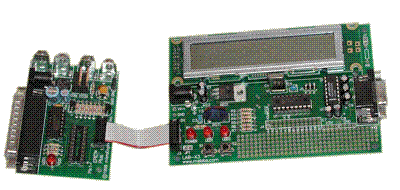
Their programmer is the EPIC Plus PICmicro Programmer. It is the thing on
the left hand side of the picture above. And one of their Demo/Lab
boards is the LAB-X3 shown on the right. Together they form the
LAB-X3 Bundle
which they sell at their web site for $199.95.
This package pretty much meets my requirements very nicely. It has a programmer that can be used by itself to program most of the serially programmed PICs (all the one’s I’m currently interested in) and while the socket on the programmer only programs 8/14/18 pin PICs, you can by an adapter that lets you program other variants (both 28/40 and 44 pin PLCC varieties). The variety of I/O is outstanding on this board with everything from buttons and LEDs (pretty typical) to a 2 line x 20 character LCD module. The downside here is that the I/O devices are all connected to various pins of the PIC socket and there doesn’t appear to be any way to change the pin assignments. Fortunately, some of them make sense like the RS–232 port is connected to RB1 and RB2 which happen to be the hardware UART on the 16F628, however the servo connector is attached to RB6 and not RB4 which is the CCP1 pin on the ’628. Why CCP1? Well if you want to play with the PWM function or input capture you can’t do it easily on the pin its attached to. This one is egregious enough that I’ve gone and cut the trace and re-routed it.
The other area where both of these boards are somewhat lacking, are the clock sections. As the PIC is extremely flexible on how it can do clocking it would be nice to have an experimenter’s board that allowed you to try all of them. Perhaps with jumpers or something.
This package connects to your PC via the parallel port. This is great if you don’t have a printer hooked up there, less useful if you do. Further it didn’t recognize my USB parallel port so you’re stuck using one in the box. Clearly the “next generation” programmers should be USB. This would allow them to work on either a MAC or a PC, have plug-n-play compatibility with a lot of PCs and laptops out there, and be fast as well.
Getting back to the servo connector for a minute, the reason I really want it connected to CCP1 is so that I can use it as a servo “input.” not an output like most folks seem to use them. I want to capture the pulse coming from an R/C receiver and then send out commands via the serial port based on what comes in. This is my current design target for the ’628 so this board came really close to having exactly what I needed on it. Now it will :-)
The other bit of weirdness is that the potentiometer is connected to RB0 rather than one of the Analog pins. Now I know it is useful to learn how to do a “fake” A/D conversion using a digital pin, but there should at least be an option to connect it to an analog pin. The LCD is connected to the Port A pins where the analog lines live. Very strange.
Following the A/D is the push button. A general purpose push button and its attached to RB7! ? Why not RB0? You see RB0 also serves as the external interrupt pin on the PIC. With the button on RB0 you can do experiments where you use an interrupt facilitated by a button press to cause something to happen. As it is you can still use ‘interrupt on portB change’ but it seems strange none the less. Perhaps the A/D conversion uses the interrupt capability or something. My vote, at least swap the pins the Pot and Button sit on!
The complete list of peripherals you get are:
- Reset button
- Push button
- Potentiometer
- 2 LEDs plus power LED
- 2 line by 20 character LCD module
- RC servo connector
- RS232 interface
And of course on the ’628 you can re-program RESET as a general purpose I/O so that lets you use it as another button.
Clearly there are a lot of cool experiments you can do with this board and learn quite a bit about the PIC. One down side of this set up is that both the programmer and the board have their own plug in wall warts (wall transformers). What’s up with that? There is a jumper where the 5V from the programmer could power the LAB-X3 but they document that you should not do this, it overloads the 5V on the programmer. This is because they are still using linear regulators on the programmer when a simple Micrel switching part could give them 5V @ 1.5A in the same space with only 3 components Then you could pass through the 5V and need only one transformer. Sigh.
After using the EPIC programmer for a while I’ve uncovered another issue. If you leave the programmer connected to the LAB-X3 when your PC is “off” or the programmer is powered down, it prevents the LAB-X3 board from running. It gets a bit annoying to plug and un-plug it when you don’t want the EPIC interfering. The Microchip module does not seem to have this issue.
However, in spite of its obvious shortcomings, its actually very very close to be the ideal product for what I wanted. I’m glad I bought it and will consider making it a standard setup for teaching PIC assembly.
The Microchip MPLAB-ICD in circuit debugger
Microchip has a long tradition of providing inexpensive tools that engineers and hobbiests can use to learn about their parts. I cannot stress how important this is to you chip marketing types. Changing architectures is expensive and time consuming. You may have the best chip in the world but I’ll be damned if I’m going to spend $4000 on development tools to “try it out and see.” Further, the 30 day demo license is a crock. Give us free or reasonably priced tools so that we can play with your chips for 6 months to a year. Document how they are programmed so that anyone can build tools for them. Remember, you sell chips, not software. And when you give away your software, what is the worse that could happen? We could design in your chips. How horrible is that?
Microchip has lead the way in giving away good free tools and reasonably priced development hardware. That policy is paying of handsomely in the tech-tanked economy of the 21st century where TI, Xilinx, Motorola, and Intel are all having soft sales and weak earnings while Microchip is plugging away, growing steadily and paying big dividends to the engineering community that decides to design them in. Way to go Microchip!
Microchip’s current product in this “tutorial/programmer/trainer” thingy market is the MPLAB-ICD. Now the claim to fame for this board set is that you can do “in circuit debugging” which is nearly like in-circuit emulation but not quite. It sells for $189 from Digikey (more from other distributors) and there is a $159 version that doesn’t have the power supply. I don’t know about you, but I wish someone would standardize on a particular type of wall wart. I’ve got at least 10 for various things, never very useful when I need to run multiple devices from an outlet strip.
If you recall some of the original Microchip programmers from Parallax and others, they often had the ability to put the programmer into the circuit for the DUT (Device Under Test). Software on the host computer (an Wintel PC type box) could run the simulator with the I/O pins connected to the real circuit. This allowed some ability to debug your programs interactively. This was especially popular with the PIC16F84 as that chip could be erased and reprogrammed in-place.
Well since that time Motorola has made a lot of converts to “BDM,” or Background Debug Mode, where the processor runs a debugger at the same time it runs the user program. The debugger allows things like breakpoints etc in your “ROM” code and generally is easier than the assemble/burn/test/assemble/burn/test cycle that it replaced. Now Microchip has gotten on the bandwagon figuring out that with a bit of software in the PIC16F87x series chips, and a cable connected to it, you can do very much the same thing. All it takes is a quarter-K words of program space and a few bytes of RAM. The result is the MPLAB-ICD.
The good news is that this is a really good way to develop PIC code as you can do a break point, see the contents of SFRs and run at nearly full speed (very nearly if you are actually running without any watch points). The bad news is that this board is optimized for PIC16F87x devices. What that means is that if you want to program the 16F628 you are pretty much out of luck. Further, while the software in the form of MPLAB 5.4 is pretty good, you can’t easily extract the MPLAB-ICD portion so if you’re not interested in giving up your current editor for the Microchip one, then you’re in something of a pickle. However, moving on to the hardware, this is where the MPLAB-ICD has some definite plusses and minuses.
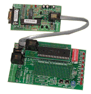
The MPLAB-ICD hardware comes as three pieces;
- The MPLAB-ICD module which connects to your PC’s serial port and has a 6 pin connector.
- The MPLAB adapter, which connects to the module and holds a PIC16F877 and has 40 pins coming off the bottom of it. This you can plug into the “target” circuit and debug it.
- The PICDEM board (made by Advanced Transdata) that the adapter plugs into.
The whole thing is actually sold by Advanced Transdata [Update: Jan/2013 these guys are out of business] for a bit less ($164 w/ Power) However if you get it from them you don’t get the printed documentation for MPLAB, the disk with all of Microchip’s technical data, the MPLAB software on CD, and a fancy box :-) Strangely, the one manual I really wanted from Microchip was the Midrange MCU manual and they don’t include that one. Not even the PIC16F87x datasheet (except on CD-ROM) which seems a bit cheesy.
The first thing I really like about the ICD is that it uses the serial port rather than the parallel port. This is a win because a spare serial port is more common than a spare parallel port on my systems at home. Again, the ideal would be a USB version since adding a USB hub is pretty trivial and you get hot plugging as well. I also like the RJ11 plug (like a telephone plug) between the board and the module as it is easy to make longer cables if you needed to.
On the peripherals side however, the PICDEM board that comes with the ICD takes little advantage of the copious I/O capabilities of the PIC16F87x family.
The complete list of peripherals are:
- Eight LEDs connected to RC0 thru RC7
- Two Pushbutton switches, one connected to Reset/MCLR and one connected to RB0.
- One Potentiometer connected to RA0.
- An un-populated RS–232 interface connected to RC6 and RC7 (these are the hardware UART pins)
At least the Microchip/Transdata board gets the connections right. Pushbutton to RB0, check. Potentiometer to an analog input, check. RS–232 to the UART pins, check.
But then the LEDs are all connected to port C. This means that two are shared with the unpopulated RS–232 interface. Weird. Since the 16F87x has two CCP/PWM units it would have been nice to hook one of them to a beeper or something. But not here. So while there are number of experiments you can do with the PICDEM board, in order to actually learn something from it you’ll need to add additional hardware.
Now the one feature that the ICD set up has over the LAB-X3 set up is that the “module” that is used with the PICDEM board can be plugged into a solderless breadboard for example and you can have any I/O you want at your fingertips. This is a bit more expensive of course but might give you what you need in the hardware resources department.
Setting up and using this board is pretty straight forward. Further, I talked to it through a USB serial port with no problem so that kinda-sorta gets you to a USB development option.
The other feature of this board is that while it has an RC network to produce the clock (remember the PIC16F87x doesn’t have an internal oscillator) it also has a socket for one of the clock “cans” that are 5V in, TTL clock signal out. I installed a 4Mhz clock to get stable run times. The debugger had no problem with this at all.
On the conspicuously absent front, there wasn’t any information in the manual (or examples) showing how to do interrupts. This makes me wonder if the “debugging” mode is using interrupts in its operations.
Summary
So between the relative paucity of I/O devices on the PICDEM board with which to play with, the inability to program chips other than the PIC16F87x, and the relative difficulty of using the ICD software outside of MPLAB. I have to say that I prefer the LAB-X3 board over all. Your mileage may vary of course. The in circuit debugging may be critical to future designs however so I am glad that I have the ICD.
Another, but perhaps non-trivial thing about the LAB-X3 is that after you’ve learned what you can from it, it easily turns into a serial port to two line LCD display for other projects. Those sell for > $100 so your costs aren’t as steep as you think if you also need one of these.
The absolute best way to get the MPLAB-ICD is to attend one of Microchip’s training seminars. I believe the advanced seminar costs $99 and you get an ICD to take home. You can also get the “bare bones” ICD from Digikey for $99 without the books and cables etc. Just the ICD and the module.
Were I to design the ideal “PIC Trainer” I would start with the EPIC Plus programmer, make it connect via USB and add a simple switcher regulator to it so that it could supply 5V to a target board at reasonable currents (say 500 - 750mA). Then on the LAB-X3 board I would provide a jumper block that connected the peripherals to the pins of the PIC rather than having them hard wired. That way they could be moved around without have to cut traces and solder new wires on the bottom. By default, I would put the push button on RB0, the Potentiometer on RA0, and the Servo connector on CCP1. Of course the cheap solution would be to put the holes for the jumper block (probably a 12 x 2) and have traces connecting them. Then the enterprising user could cut the traces, install the jumper block and have fun, but the board wouldn’t be any more expensive to produce for the “normal” case when hard wiring was ok.
Finally, I would provide a PLL synthesized clock that would allow me to select different clock frequencies easily, and jumpers to allow the clock pins to be used as I/O’s instead. A PIC board I have from the “old days” is the Depew Engineering “PIC Prototyper” has this feature and its really handy. (Its also on the latest FPGA boards from BurchEd)
| Feature | LAB-X3 Bundle | Microchip MPLAB-ICD | Advantage | Cost | $199 | $189 | Lab-X3 since you get more peripherals for your money. |
|---|---|---|---|
| Base Chip | PIC16F628 | PIC16F877 | Microchip as the '877 has more I/Os. |
| PC Interface | Parallel | Serial | Microchip wins as finding a spare serial port is often easier. |
| Software Bundle | EPIC Programmer, Assembler | MPLAB w/ Assembler, Debugger, IDE, etc | Microchip, the software is full featured but you can't customize it. But then again, the Microchip software is free and can use with the LAB-X3. |
| Can program other PIC variants | Yes | Some | LAB-X3 Bundle, with ZIF add ons can do most of the serially programmed chips, Microchip only does '877, 876, etc. |
| Clock Options | Fixed at 4Mhz (Crystal) | Either R/C or user supplied clock "can" | LAB-X3 Bundle as their clock is at least stable. Adding the clock can on the proto area is straight-forward. |
| I/O Peripherals | LCD, Serial port, LEDs (2), Push Buttons (2), Potentiometer, Servo plug. | LEDs (8), Push Buttons (2), Potentiometer, Optional Serial. | Definitely the LAB-X3 wins here, more experiments can be done "out of the box" but the fixed I/Os is a pain. |
| Dedicated I/O's | Yes, all peripherals are hard wired to specific pins. | LEDs can be "disconnected" by operating a dip switch. Buttons and Pot are hard wired. | Mixed, probably Microchip gets the nod. |
| Power | Dual wall warts (one for the LAB-X3 and one for the programmer. | Single Wall Wart for both ICD and demo board. | The single wall wart is easier, however the EPIC programmer and LAB-X3 can operated independently. Finally the EPIC programmer can use dual 9V batteries for "on the go use." |
| Other features | Can program other chips with ZIF adapters. | Can be plugged into target circuit (if it takes a PIC16F87x) and do in-circuit debugging. | Being able to debug "in circuit" can be really helpful. |
Summary: Both systems offer advantages and disadvantages, of the two if I could only buy one it would be the LAB-X3 bundle because it allows me to program a variety of chips and learn about the PIC architecture. If I knew that I was only going to use 16F87x chips I might be inclined to go with the MPLAB-ICD.
Fixing the LAB-X3
As I mentioned above it is unfortunate that the LAB-X3 hard wires some of its I/O pins to particular pins on the PIC. Specifically I am interested in using the CCP1 pin of the ’628 to capture servo signals coming from a radio receiver. I’m planning on using the input capture function of the CCP module to do this. As delivered the LAB-X3 connects the “E” pin of the LCD to that pin, and connects the servo connector’s pin to RB6. Not good.
WARNING: THE FOLLOWING ACTIONS IMMEDIATELY VOIDS YOUR WARRANTY AND MAKES THE LCD SUPPORT FOR YOUR LAB-X3 NO LONGER WORK! IF YOU ARE USING PICBASIC AND THE LCD, DO NOT MAKE THIS MODIFICATION. IF YOU SCREW UP, YOU ARE OUT ONE BOARD. I DISCLAIM ALL RESPONSIBILITY FOR YOUR ACTIONS.
This “fix” involves cutting two traces on the printed circuit board and adding two jumper wires. If you are uncomfortable doing this then do not attempt it. You will need some 30AWG (wirewrap) wire, a fine tip soldering iron, and an exacto knife. Refer to the picture below (you can click here for a close-up)
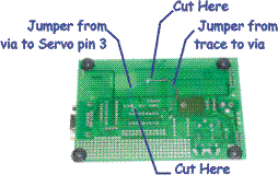
The LCD module’s E signal comes straight across the back of the board to a VIA where it transitions to the other side and runs to pin 9. So step one is to cut this trace between the VIA and the LCD. (I use an Exacto knife and a magnifying glass/lamp combo). Once you have cut the trace, scrape off some of the solder mask to expose the copper trace on its way to the E line. The second trace to cut goes between the 3rd pin on the servo connector and pin 12 of the PIC. When looking at the bottom of the board, make the cut after the fork in the trace, on the particular trace that forks to the left toward the servo pin. The fork to the right connects the pin to the programming connector so DON’T CUT IT.
Now you’re ready to add the jumpers. Jumper #1 (blue in my picture) goes from the servo pin to the VIA hole. The VIA hole is easy to solder to as is the pin. Leave about 1/16" of wire on each end of the jumper that is not insulated. Put that next to the servo pin and with your iron re-heat the joint until the solder there flows around the wire and the pin. Next take the other end of the wire, stick it partway down the VIA hole and then add a small bit of solder. Voila, the Servo pin is now connected to pin 9 (you can verify with a continuity setting on a multimeter)
Jumper #2 (the red wire) is similarly placed, only this time you have to solder it to the trace (note that you could solder it to the E pin of the LCD but then it would have farther to travel). Heat a bit of solder and put it on the trace you exposed. Leave a “bump” of solder there. Now a piece of wire with about 1/16“ of it exposed on the bump and use your iron to ”push it down" into the solder. When the solder reflows, take the iron away and blow the joint to harden it. Now put the other end of that wire into the VIA that is in the trace from pin 12 of the PIC. Solder with a small bit of solder and now the LCD’s E line is hooked up to pin 12 (RB6) of the PIC.
Make sure you don’t have any left over solder or bits of trace on the board, put a piece of clear tap across the wires to keep them in place (a small dab of epoxy is used in “real” re-work shops but tape will do).
Further Notes
One of the side effects of making this modification is that the EPIC programmer does not come up in a state that lets pins B6 and B7 operate “normally”. That is it holds them in the low state. Thus by putting the E line of the LCD on B6, it becomes impossible to write to the LCD if the programmer hasn’t recently been used to download a program. This is a bit annoying, not generally a problem in use because you are typically either in a download/test cycle or running without it, but an annoyance none the less.
Update 12/03: One of the “issues” with parallel port programmers is that you can blow out your parallel port if you hook them up when the computer is on. I experienced this first hand by blowing out the parallel port on my Asus N78NX today. Be careful, and better yet, if you are using a parallel port programmer invest in a separate parallel port card don’t use it on a laptop.
I have a program that measures the width of the input pulse in Microseconds and displays it on the LCD read all about it.
–Chuck McManis, Dec 2001.