In this
article:
Source Code
License
Navigation:
HomeHardware
Software
Techniques
Controllers
Reviews
Index
Description
This is the solution I came up with for the HEX Counter problem. See Image 1 below for a drawing of the “logical” schematic of the result.
The specification called for an 8 bit counter that displayed its count on two hexadecimal displays. The input is again 24Mhz and the counter operates at 10Hz.
Things I learned from this project:
- I learned that Synopsys FPGA Express doesn’t allow you to specify constants in entity instances.
- I originally was going to count in decimal, but that is a bit more difficult :-)
- More complicated circuits are easier if you decompose them into functional blocks.
- You can’t gate a clock with an AND function in the process block.
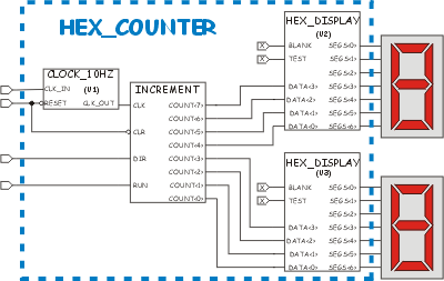
In the schematic above, the various logical parts are labeled as they are in the VHDL code. The CLOCK_10HZ part is “U1”, the HEX_DISPLAY parts are “U2” and “U3.” The process block that defines the counter is labeled “INCREMENT.”
Note that the BLANK and TEST inputs are not connected. In the VHDL code I had to use a bogus signal declaration in order to achieve that effect. With the WebPACK compiler (XST VHDL) you can just put the constant ‘0’ or ‘1’ in the port map and it does the right thing with them.
The Source Code
library IEEE;
use IEEE.STD_LOGIC_1164.ALL;
use IEEE.STD_LOGIC_ARITH.ALL;
use IEEE.STD_LOGIC_UNSIGNED.ALL;

entity hex_counter is
    Port ( src_clk : in std_logic;
           dir : in std_logic;
           run : in std_logic;
           clr : in std_logic;
           display0 : out std_logic_vector(6 downto 0);
           display1 : out std_logic_vector(6 downto 0);
              digit : out std_logic_vector(7 downto 0));
end hex_counter;

architecture behavioral of hex_counter is

    component hex_display port (
        test, blank : in std_logic;
        data : in std_logic_vector(3 downto 0);
        segs : out std_logic_vector(6 downto 0));
    end component;

    component clock_10hz port (
        clk_in, reset : in std_logic;
        clk_out : out std_logic);
    end component;

    signal clk : std_logic;
    signal count : std_logic_vector(7 downto 0);
    -- bogus
    signal xx : std_logic;
    signal rotator : std_logic_vector(7 downto 0);

begin
    xx <= '0'; -- this is a "false" constant...
    -- create instances of the clock divider and displays, and then attach
    -- them to the signals we are using.
    u1: clock_10hz port map (clk_in => src_clk, clk_out => clk, reset => clr);
    u2: hex_display port map (test => xx, blank => xx,
            data => count(7 downto 4), segs => display0);
    u3: hex_display port map (test => xx, blank => xx,
            data => count(3 downto 0), segs => display1);

    disp: process (clk) is
    begin
        if (clr = '0') then
            rotator <= "00000001";
        elsif rising_edge(clk) then
            rotator <= rotator(6 downto 0) & rotator(7);
        end if;
    end process;

    digit <= rotator;

   increment: process (clk, clr, run, dir) is
    begin
        if (clr = '0') then
            count <= "00000000";
       elsif (rising_edge(clk) and run = '1') then
            if (dir = '1') then
                count <= count + "00000001";
            else
                count <= count - "00000001";
            end if;
        end if;
    end process;
end behavioral;
License

This work is licensed under a Creative Commons Attribution-NonCommercial 3.0 Unported License. You are free to play around with it and modify it but you are not licensed to use it for commercial purposes. Click the link above for more details on your rights under this license.