In this
article:
Navigation:
HomeHardware
Software
Techniques
Controllers
Reviews
Index
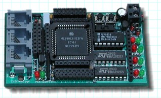
The Miniboard was designed at M.I.T. by Dr, Fred Martin and Randy Sargent. It was a direct descendent of the 6.270 board which was used by the MIT 6.270 mechatronics class. Small and compact it depends on the Motorola MC68HC11E2 processor which has both 2K bytes of EEPROM and 256 bytes of RAM on chip. This is just enough space to run a small program and keep a few variables.
Like the 6.270 board, this board uses the LM293D bipolar H-bridge chip and provides four motor outputs. The ports are wired so that they can drive stepper motors as well if you wire them up as half bridges. The red and green LEDs on the right side of the board read out the motor state.
In addition to the motor drive, 8 A/D converters are available (8 bit), 8 digital I/O pins (either direction), and 8 pins that are either timer capture/outputs or general purpose I/O. A speaker can be attached for hearing beeps and squawks, and this was my first experience with the now infamous ’one-transistor single-ended half-duplex RS–232 interface."
The quantity and versatility of the I/O makes this a really nice robot controller, however the lack of RAM becomes a serious limitation fairly quickly. This was the main processor for my Cougar robot but I found I could not keep both the ultrasonic, motor PID, and the IR detector routines in memory at the same time.