In this
article:
So about the software ...
SDRs Today
Navigation:
ParentHome
Hardware
Software
Techniques
Controllers
Reviews
Index
Introduction
In 2007 I attended a conference where Matt Ettus (the founder of Ettus Research) gave a fascinating talk on the latest software radio that Ettus Research had produced called the Universal Software Radio Peripheral or USRP. For the same reasons that I found building hardware out of software with FPGAs exciting, I found the possibility of creating a radio out of software equally compelling. It was super expensive though. At that time it cost about $3,000 to get just the basic set of parts needed to do the “interesting” bits. I filed it under “someday when I’m rich and have nothing better to do.”
Jumping ahead seven years, in 2014 I read about a clever hack that allowed you to pull “IQ data” (and no I didn’t know what they meant by that) from a USB device that was supposed to be a digital TV adapter. With that data you could make your own software defined radio.
I liked the last bit (make your own SDR) and the price was pretty cheap, about $40 at the time. So I ordered one that had been modified and played around with the basic “build your own FM radio” project which is the “Hello World” of software radios.
Once I had a toe in the water, I found a bunch of material from Amateur Radio operators (HAMs) on “software radio” and it was very different from the hobbist / hacker material. Using sound cards to modulate and demodulate signals, HAMs had been doing this stuff since the turn of the century (late 1990’s and early 2000’s) and they had their own set of ideas about what was and what wasn’t SDR.
So what is SDR? And what is it not? That turns out to be a great jumping off point for playing around with this stuff and so that is where I will start in this series of posts.
What is Radio Mr. Peabody?
I would guess that a majority of the people you asked, would know what a radio is. What the would be less clear on would be how it does what it does. What is more, while nearly everyone it seems is familiar with radio receivers, not everyone is familiar with radio transmitters. While there are many similarities, there are also some crucial differences that go beyond that fact that one receives and one sends. Let’s start with the easy case, the receivers.
A radio receiver is a device that receives “signals” over the air. These signals are actually self propogating electromagnetic waves. My first experience with radio, was listening to the AM/FM Radio in my parent’s stereo cabinet. I understood that somewhere there was someone “transmitting” a radio signal, and that somehow this box in the living room was “receiving” that signal, and that it sounded better if it was “FM”. What I didn’t understand was how it did that. Let’s talk about that first.
As it turns out, AM and FM radios are pretty straight forward things. The simplest design for an AM radio, called a crystal radio is nothing more than a germanium diode, a coil of wire, a capacitor, and a speaker of some sort. You can read more on Simon’s excellent site on how it works, but I will do a quick summary.
Radios typically have two frequencies of interest, the carrier signal (which we will call the RF signal) and the modulated signal (which we will call the baseband signal). The carrier, is the radio frequency of the radio station. The baseband signal is the representation of the data or audio that the transmitter is sending out. A radio transmitter mixes the RF carrier waveform with a baseband signal. This is called modulating the carrier waveform. The receiver reverses the process to extract the baseband signal from the carrier, this is called demodulation. At its simplest, amplitude modulation or AM is a process where the baseband signal (audio in the case of AM radio stations) feeds a voltage controlled amplifier, which is amplifying the RF carrier waveform. The result is an RF carrier waveform that changes in strength in proportion to the modulating signal.
If you build a resonant circuit, one that wants to oscillate at a particular frequency, and fed it from an antenna which was exposed to an RF carrier wave at the resonant freqency, then the amplitude of the output of that circuit would change in proportion to the sound used to modulate the carrier originally. If you then rectify that signal (the purpose of the diode), and used a capacitor to smooth the changes in amplitude to something in the typical audio frequencies, you recover a good approximation of the original signal. You can feed that approximation into a speaker and hear a good reproduction of the sounds as they were originally modulated at the transmitter.
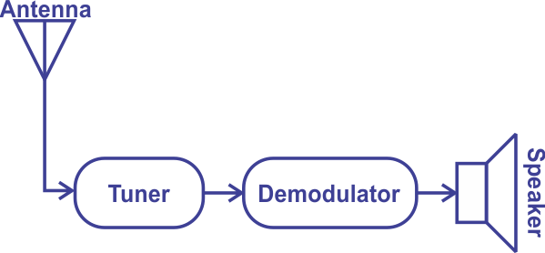
These are the fundamental components of any radio, one is a circuit for converting RF energy into a varying voltage (the antenna circuit), one is a circuit for selecting a specific carrier frequency (a tuner circuit) out of all the energy, one to demodulate or detect (a detector circuit) the baseband signal, and finally a circuit to convert the demodulated signal into something you can use like an audio output or a serial output. A picture of that is shown below.
So about the software …
It really is that simple, but withing that simplicity lays some interesting complexity as well. Lets look at each step along the way and see where we can add code, starting with the first places, and ending with the last places.
The Demodulator
The early days of SDR in the Amateur community would use a conventional receiver and tuner to receive a signal, and then take the baseband signal and feed it into the sound card of a personal computer. The sound card, sampling the baseband signal at 24 kHz or even 48 kHz would feed that data into a program that could demodulate it into its original audio or RTTY data. The limit of 48 kHz of bandwidth limits the kinds of signals you could demodulate.
Perhaps one of the biggest drivers for this was packet radio, developed in the 70’s and it really took off in the 80’s. Originally it used computer modems (modulator/demodulators) that used frequency shift keying (FSK) like the Bell 202 modem. These modems were expensive, had finicky filters, and were hard to get. But by the late 90’s, the CPU power of home PC’s was being used to implement modulation and demodulation in software, and this was quickly adapted by the Amateur radio community for use in packet radio.
PCs were doubling in performance every year or so, and the field of digital signal processing which had started out using specially built digitial signal processing chips, was becoming more and more useful on the PC. So the first “age” of software radio really got going when people could experiment with new modulation schemes, and use software to make audio filters that were an order of magnitude better than their hardware counter parts.
Having a PC with a good sound card became a standard piece of gear in HAM shacks all around the world.
The Tuner
Tuners were the topic of the 2007 talk I attended. Specifically analog to digital converters had been getting fast enough that with an FPGA to buffer the data coming from them you sample signals that had 5, 10, even 30 MHz of bandwidth. That changed a couple of things, for one, if you look at the FM radio band it is only 20 Mhz wide, from 87.9 to 107.9 MHz. So an ADC that could digitize at 20 MHz could potentially see every FM station all at the same time.
What was a bit more interesting was 802.11 WiFi signals, they had 22 MHz of bandwidth. That meant it was possible to decode them using a software only solution if you could get all that data into your PC.
As ADCs got faster it became simpler to build a system that sampled a “chunk” of spectrum (this is sometimes called the ‘stare’ to suggest all the spectrum the radio can see at one go) and that meant that even if you tuned this in coarsely, you could use software to pull out the precise area of the spectrum you were looking for. This was important because one of the hard problems in radio is making reliable and steady frequency sources or oscillators.
The Antenna
You might think that an antenna is just a wire (or more precisely a conductor) which is set up to be influenced by any passing electromagnetic waves. Hardly something you would want to add software to. You might be surprised.
Antennas, especially at frequencies below 250MHz, are arguably the most important part of the radio. As you get closer to 0 Hz (DC), there is more noise and interference in the spectrum. This is why lower frequency antennas are tuned to be maximally sensitive to the frequency of interest, and less sensitive to other frequencies. Either with a capacitor or a coil with an adjustable “slug”, the antenna can be tuned for the frequency of interest.
Antenna selectivity is improved by making them directional as well. A directional antenna, pointed in the direction of a transmitter, will get more signal and less noise which results in a higher signal to noise ratio or SNR.
Software is used in antennas to change their configuration without moving parts. Either by using switches to select between elements, or by enabling or disabling mixers and couplers in order create constructive interference to improve antenna gain. Arrays of antennas which can be selectively enabled and mixed are called “phased array” antennas. These antennas have controllers that use different antennas in the array that are either in phase or out of phase with the signal direction of interest, to cause the antenna to be maximally sensitive along a narrow vector. RADAR and cell phone towers use techniques like this to increase their range or sensitivity without increasing their power.
For the most part however, at least in lower end “hobbyist” software radios, the Antenna is just a conductor. I have used this antenna very successfully in my SDR experiments.
SDRs Today
Today (well as of March 2019), a “software radio” is one that