In this
article:
Jumper Building Tutorial
Navigation:
HomeHardware
Software
Techniques
Controllers
Reviews
Index
Introduction
“Hey, where’d you get those cool jumpers?” Is a question I get quite often. The cables in question are the wires I use to hook things like the BASIC Stamp 2 to a proto-board. The answer is, I make them myself. It isn’t hard, and you can’t actually buy them anywhere so you don’t really have a choice now do you?
Description

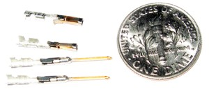
A typical jumper cable is shown to the right. These are actually a commercial form from JameCo (part number 126359) You will notice that they have pins on both ends.
That’s great if you’re going to be wiring up stuff on a typical proto-board but most microcontroller boards use jumper blocks, not jumper sockets (note that Fred Martin resisted this trend with the Miniboard and Handyboard).
Anyway, I searched for a long time to find a way to make a jumper that was a socket on one end and a pin on the other end. That would let me plug jumper block pins found on microcontrollers into a proto-board. I was finally successful using the pins sold for DB25 connector hoods. Yup, those make your own serial cable kind of things.
From Mouser Electronics I ordered a bag of #571–7486104 crimp on sockets and a bag of #571–7483334 crimp on pins. To build a cable you decide if you want it socket-socket, pin-pin, or pin-socket and get the appropriate crimp-ons. Next you cut a length of 24AWG wire, and cut two .75“ pieces of small heat shrink (3/32” or 1/8“ works great). Crimp on the connectors, then slide over the heat shrink and shrink it. Leave about 1/4” of pin exposed but on the socket end line the heat shrink right up to the edge. Voila’ you’ve got a cool jumper cable.
Now for the stuff you don’t know but need to :-)
Pick the same color wire for each type of jumper (pin/pin, pin/socket, socket/socket), that way when you grab one out of your tool box you’ll know what you’re getting.
At each end of the cable, use a marker to draw a number of evenly spaced lines around the insulation area. This banding allows you to locate the other end when you’re connecting multiple cables together. If you are really tricky you can use wide and narrow lines, or adhesive “flags.”
Don’t try to force the connector socket over a pin, if it isn’t going smoothly then you aren’t lined up!
Keep these simple rules in mind and you’ll get a great deal of use out of these cables.
Jumper Building Tutorial
Ok so you’re convinced? Well for the Adafruit Forums I wrote up a short tutorial on how to make these jumpers. I’ve reproduced that here.
So I promised to talk about making jumpers and while it was asked in the shield sub-forum I felt its pretty generic so decided to post here, if you would like it somewhere else ladyada it is within your power to move it :D
So a lot of times when you are using breadboards and/or Arduino’s and/or evaluation boards Etc. There are connectors brought out to access the functions on the board. Far and away the most common form of connector that is used is a 0.025“ square post type, separated by 0.100” (center to center), in a single or dual row. Sometimes the connectors are female (as they are on the Arduino) and sometimes they are male (as they are on the STK 500 for example). But they are all pins and sockets with the common property of pin size and spacing, varying only in the sex and number of pins.
Here on the Adafruit site and elsewhere people sell “breadboarding” jumpers which have a pin on each end of a wire, and sometimes they sell jumpers that are female on both ends, but nobody seems to have jumpers that are female on one end and male on the other. Anyway I decided a long time ago that it would be beneficial to make my own jumpers and started doing so. When I first wrote about it, the simplest way to make these jumpers was to buy the crimp on pins and sockets that were used for “high density” D-shell connectors. A number of people sell them (Digikey, Mouser, Frys, many surplus places) and they work fine but they are slightly smaller in diameter than the “real deal” pins and so sometimes make poor connections or have a hard time staying in place in your breadboard. Not too long ago however Molex/Waldom started selling the parts to make their “CC” connectors and we can exploit that to make our jumpers.
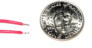
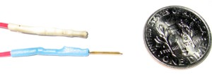
Step one is to get some of these jumper ‘ends’ and a solid source for them is Digikey. They sell them under part number WM2515-ND for the male connectors and WM2512-ND for the female one. Here is a picture of them next to a dime.
(Sorry for the poor contrast, my macro photography isn’t what it should be.) That is two female and two male connectors next to a US ‘dime’ coin (its about 18mm in diameter). You can manually crimp them with a pair of needlenose pliers like I do or get the special “crimping tool” for a bunch of money. Next you need to prepare some wire.
Selecting and Preparing the Wire
I like to use stranded wire because its flexible and lasts longer. I like the Beldin type 9923 stranded hookup wire but any stranded wire that the local electronics shop sells in a suitable gauge will work. These pins will accept wire between 20 AWG and 24 AWG, I tend to use 24AWG because its thinner and lighter but 22 AWG can be a bit more durable.
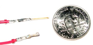
Two things of import about stranded wire is that the insulation will have a thickness which will be important later and a number of strands. The cheap 24 AWG wire (which works well) is 7/32 (that is 7 strands of 32 AWG wire). If you can get it as tin coated copper (common in hookup wire) then that will make soldering it easer. In either case you will cut your wire to length, strip off a small bit at the end and then use solder to cement the ends together (this is called ‘tinning’). I tend to strip off about 3/8“ (about 10mm), tin it, and then clip off the excess leaving behind about 1/8” (about 3mm). There is a picture of the prepared wire next.
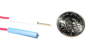
Crimping and Soldering on Pins
Now that you have the wire prepared, lay it into the area of the connector which gets crimped and crimp the connector. The connector has a wider area in the back which is used to crimp to the insulation and a narrower crimping area ahead of that to crimp to the conductor. I tend to use a magnifier when I crimp these so that I can be sure I’m squeezing the edges over the wire and not closing them onto empty space. Once the crimp is closed I use my soldering iron to heat up the join and let the solder flow around in there, creating a good (and permanent) electrical connection. I took a picture of that too but its kind of hard to see clearly.
Ok, so now we’ve got pins crimped and soldered on to our wire, time to finish them with heat shrink and make them look professional.
Finishing Touches for Reliability and Durability
To make sure that nothing bad happens to the connection we cover them in heat shrink tubing. 3M makes the tubing in several colors and Mouser will sell you an assortment. You need two pieces, each .75“ (19mm) long to finish the ends of your jumper. So things to know about heat shrink tubing, it starts at one diameter and when it is exposed to heat it ”recovers“ to a much smaller diameter. You want to get tubing that comfortably fits over the wire and crimped on connector, but isn’t so big that when it is shrunk its still loose. In these pictures I’m using their smallest tubing (1/16”) but on jumpers where the hook up wire had fairly thick insulation I’ve had to use 3/32" tubing.
Another thing you will notice is that I’ve used two different colors and this turns out to be useful. Since you’re connecting these jumpers from one connector to another, you may find you need 5 jumpers from connector A to destination B, having different colored wire would help you figure out which is which, and having different colored heat shrink does the same thing. Beldin has 10 colors of wire, 3M has 6 colors of heat shrink. That means you could have sixty! 6" long jumpers where you can tell which one is which. This is critical for big setups. However if you’re unable to get different colors, an alternative strategy I’ve used is yellow wire (common) with black heat shrink (very common) and on each wire I used a sharpie to draw a number of bands at each end, so the jumper end that has 4 bands at the end your looking at also has 4 bands at the other end. Anyway, being able to tell jumpers apart is really really useful. Here is a picture of the heat shrink on the pins before shrinking.
So two important points here about the heat shrink, you want it to be just behind the end of the female pin and you want it to cover the entire solder/crimp area. That is what dictates the .75" size, you can have it longer but shorter than that and it won’t cover everything you need covered. If the heat shrink overhangs the end of the female connector, then when it shrinks it will cover the hole which will make it harder to use. The sign of a good match is that once you shrunk the tubing you can see the outline of the crimp connector as shown in this next picture.
As you can see in the picture the bumps of the solder point and where the pin is crimped around the insulation is clearly visible. Now I tend to use a butane lighter (sold in the US as an ‘Aim-n-Flame’ which sounds like a weaponized SMTP script) which you can see from the picture can leave a bit of lamp black on the heat shrink. (You can impress your friends by calling it a light coating of carbon nano-particles if you’d prefer) You can also shrink the tubing with a hot air gun and that will give you a nice unblemished finish.
Using Your New Jumpers
Finally we have a picture of using it with the Proto-shield. I built the protoshield and noted that with the Breadboard in place I would have a hard time using the extra LED and Switch that was available. So I used the left over snappable header that came in the kit and soldered single pin connectors into those holes. Now with my M/F jumper cables I can attach those board resources to the breadboard easily. Here’s a picture of that
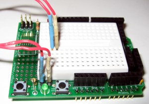
And there it is, its fairly simple and once you have the confidence of making your own jumpers you will find all sorts of cool things you can do with that talent. Enjoy,
–Chuck