In this
article:
Source Code
Late breaking news:
Conclusions
Navigation:
HomeHardware
Software
Techniques
Controllers
Reviews
Index
Introduction
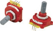
I’ve been having a lot of fun with my LAB-X3 lately. This time I wanted to figure out how to read rotary encoders. If you aren’t familiar with them, a rotary encoder looks like a potentiometer, except that instead of a variable resistor it an encoder wheel. Also, unlike a potentiometer they don’t have a “stop” point generally. Thus you can turn them around and around and around. They have become very popular on electronic equipment because you can create a “soft” control that is digital from the start. Further, because they have become fairly popular the costs have gone down such that the one I used from Grayhill is only $4.70 from Digikey ( GH3071-ND) qty 1.
Description
These mechanical encoders generate a “quadrature” signal. I don’t know the origin of the term quadrature but basically it means there are four states that this device can be in. Further, transition from one state to the next is well defined so with a simple circuit or some software you can translate the pulses into rotation movement.
The three pins on the device are A, B, and Common. Since they are mechanical they are simply switches that connect the A pin, the B pin, and then both the A and B pin to the C pin. A simple circuit for hooking this up is shown below.
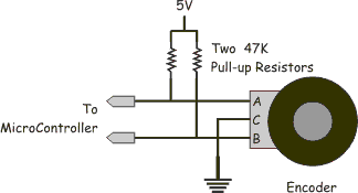
As you can the outputs will appear to be 5V when the encoder is not connecting either A or B to C and they will be at ground potential (logic 0) when they are being connected.
The output of the encoder is a two bit gray code, specifically it has the sequence
| Clockwise Rotation -> |
|---|
| 00 01 11 10 00 |
| <- Counter Clockwise Rotation |
Or more specifically, if the output is 00 and it goes to 01 you know that the encoder has moved one “tick” clockwise, if it is 00 and goes to 10 then you know it moved one tick counter clockwise. If it goes from 00 to 11 you know you missed an intermediate tick. It can be useful to flag this case so that you know your input isn’t accurate, but generally its safe to ignore it as if the knob didn’t move.
Now there are a couple of ways you can read this device, the simplest is to set your microcontroller to interrupt when ever the state of the two pins changes. Then by knowing the previous state and the current state you can tell what happened. This is easy to do with the PIC which has the ‘change on PORTB’ interrupt mode. An alternative is to hook the two pins up to input capture pins of the Motorola 68HC11. When you capture a rising or falling edge on either input you can update the position state. Finally, there is an even easier way (but its a bit risky) which is to sample the pins every n microseconds and see if their state has changed.
I chose to use the sampling technique and sample at 1Khz (1 mS per sample). My reasoning was as follows:
- We’re talking a human here who is turning this knob, and if they spin it as hard as they can they worse they can do is miss one state. Normal use is unaffected.
- If there is any “bounce” in the switch (and I’ve not detected any) then the mS sampling will cover for it.
Source Code
The code to read these is fairly straight forward, I’ll save you from digging from the full file by just pulling out the relevant bits. If you want the whole thing email me and I’ll send it to you.
I’m using the PIC16F628 in a LAB-X3 proto board. The encoder was soldered into the prototyping area with the appropriate pull up resistors. Note that you could use the ‘weak pullups’ feature on PORTB but I didn’t want to turn those on for all the pins. Anyway, as I’m not using the serial port in this example I jumper the Encoder to pins RB1 and RB2 on the PIC.
The code to set up a 1Khz interrupt from TMR0 on a 4Mhz system is as follows:
        ; * * * * * *
        ; * BANK 1 Operations
        ; * * * * * *
        BSF     STATUS,RP0      ; Set Bank 1
        MOVLW   B'0000010'      ; Set TMR0 prescaler to 8
        MOVWF   OPTION_REG      ; Store it in the OPTION register
        CLRF    TRISA           ; Now A is all outputs
        CLRF    TRISB           ; B all outputs
        BSF     TRISB,BUT_S1    ; Button S1
        BSF     TRISB,QUAD_A
        BSF     TRISB,QUAD_B
        MOVLW   D'199'
        MOVWF   PR2             ; Set PWM Register
        ; * * * * * * * * * * *
        ; * BANK 0 Operations *
        ; * * * * * * * * * * *
BANK_0:
        CLRF    STATUS          ; Back to BANK 0
        BSF     PORTB,LED1      ; Turn On LED1
        MOVLW   D'100'
        MOVWF   CCPR1L
        MOVLW   H'4'            ; TMR2 Enable 1:1 Prescale
        MOVWF   T2CON           ; Go
        MOVLW   b'1100'
        MOVWF   CCP1CON

        MOVLW   D'200'

        CALL    DELAY
        CALL    LCD_INIT
        CLR16    COUNT
        MOVLW   d'100'
        MOVWF   COUNT
;
; The last thing we do is enable interrupts
;
        BSF     INTCON, T0IE    ; Enable Timer 0 to interrupt
        BCF     INTCON, T0IF    ; Reset flag that indicates interrupt
        BSF     INTCON, GIE     ; Enable interrupts
Then you have the following in the interrupt service routine:
INTR_PRE:
        MOVWF   TMP_W           ; Copy W to a temporary register
        SWAPF   STATUS,W        ; Swap Status Nibbles and move to W
        MOVWF   TMP_STATUS      ; Copy STATUS to a temporary register
        CLRF    STATUS          ; Force Bank 0
;
; State is saved, and we've expended 3 Tcy plus the 3 Tcy (4 worst
; case) of interrupt latency for a total of 6(7) Tcy.
;
; Now loop through until we've satisfied all the pending interrupts.
;
ISR_0:
        ; ... test bit to see if it is set
        BTFSS   INTCON,T0IF     ; Did Timeer0 Overflow?
        GOTO    ISR_1           ; No it didn't, so check next thing.
        ;
        ; Process Timer 0 Overflow Interrupt
        ;
        BCF     INTCON, T0IF    ; Clear Timer 0 interrupt
        MOVLW   D'133'          ; Reset counter to get 1 Khz interrupt
        MOVWF   TMR0            ; Store it.
        CALL    QUAD_STATE      ; Check the Quadrature Encoders.
        GOTO    ISR_1           ; Nope, keep counting
ISR_1:
;
; Exit the interrupt service routine.
; This involves recovering W and STATUS and then
; returning. Note that putting STATUS back automatically pops the bank
; back as well.
;               This takes 6 Tcy for a total overhead of 12 Tcy for sync
;               interrupts and 13 Tcy for async interrupts.
;
INTR_POST:
        SWAPF   TMP_STATUS,W    ; Pull Status back into W
        MOVWF   STATUS          ; Store it in status
        SWAPF   TMP_W,F         ; Prepare W to be restored
        SWAPF   TMP_W,W         ; Return it, preserving Z bit in STATUS
        RETFIE
As you can see the TMR0 is reloaded first to insure an accurate tick rate (also TMR0 is the first interrupt checked!) Once you know you’re set to get the next “tick” on time, then you can check the quadrature state. In the ISR I call QUAD_STATE and this is written as follows:
;
; QUAD State
;
; A quadrature encoder traverse a couple of states when
; it is rotating these are:
;       00      |  Counter
;       10      |  Clockwise
;       11      |     ^
;       01      V     |
;       00  Clockwise |
;
;
QUAD_STATE:
        BCF     STATUS,C        ; Force Carry to be zero
        MOVF    PORTB,W         ; Read the Quadrature encoder
        ANDLW   H'6'            ; And it with 0110
        MOVWF   Q_1             ; Store it
        RRF     Q_1,F           ; And rotate it right.

        RLF     Q_NOW,F         ; Rotate Q_NOW Left
        RLF     Q_NOW,W         ; by two (this was last time)
        IORWF   Q_1,W           ; Or in the current value
        MOVWF   QUAD_ACT           ; Store at as the new action
        MOVF    Q_1,W           ; Get last time
        MOVWF   Q_NOW           ; And store it.
        ;
        ; Computed Jump based on Quadrature pin state
        ;
        MOVLW   high QUAD_STATE
        MOVWF   PCLAUTH
        MOVF    QUAD_ACT, W     ; Get button state
        ADDWF   PCL,F           ; Indirect jump
        RETURN                  ; 00 -> 00
        GOTO    DEC_COUNT       ; 00 -> 01 (-1)
        GOTO    INC_COUNT       ; 00 -> 10 (+1)
        RETURN                  ; 00 -> 11 (missed a count!)
        GOTO    INC_COUNT       ; 01 -> 00 (+1)
        RETURN                  ; 01 -> 01
        RETURN                  ; 01 -> 10 (missed a count)
        GOTO    DEC_COUNT       ; 01 -> 11 (-1)
        GOTO    DEC_COUNT       ; 10 -> 00 (-1)
        RETURN                  ; 10 -> 01 (missed a count)
        RETURN                  ; 10 -> 10
        GOTO    INC_COUNT       ; 10 -> 11 (+1)
        RETURN                  ; 11 -> 00 (missed a count)
        GOTO    INC_COUNT       ; 11 -> 01 (+1)
        GOTO    DEC_COUNT       ; 11 -> 10 (-1)
        RETURN                  ; 11 -> 11
INC_COUNT:
        INCF    COUNT,F
        MOVLW   D'201'
        SUBWF   COUNT,W
        BTFSS   STATUS,Z
        RETURN
        DECF    COUNT,F
        RETURN
DEC_COUNT:
        DECF    COUNT,F
        MOVLW   H'FF'
        SUBWF   COUNT,W
        BTFSS   STATUS,Z
        RETURN
        INCF    COUNT,F
        RETURN
The INC_COUNT and DEC_COUNT limit the resulting value to between 0 and 200 because that was what my application called for, however it could just as easily have kept an 8, 16, or even 32 bit absolute value. Clearly this code would also work with quadrature encoders on wheels of a robot but there you have to take into account that if your robot is moving quickly you will definitely want to adjust the sample rate accordingly!
Late breaking news:
An alert reader pointed out that I could just write a subroutine for the quadrature encoder that returned +1 or –1 or 0 and then added that to the value. To that end, the following subroutine was created:
;
; Return the value of what we should do to the value to adjust it.
;
QUAD_ACTION:
        ;
        ; Computed jump based on Quadrature pin state.
        ;
        CLRF    PCLATH  ; Must be in page 0!!!
        ADDWF   PCL,F   ; Indirect jump
        RETLW   H'00'   ; 00 -> 00
        RETLW   H'FF'   ; 00 -> 01 -1
        RETLW   H'01'   ; 00 -> 10 +1
        RETLW   H'00'   ; 00 -> 11
        RETLW   H'01'   ; 01 -> 00 +1
        RETLW   H'00'   ; 01 -> 01
        RETLW   H'00'   ; 01 -> 10
        RETLW   H'FF'   ; 01 -> 11 -1
        RETLW   H'FF'   ; 10 -> 00 -1
        RETLW   H'00'   ; 10 -> 01
        RETLW   H'00'   ; 10 -> 10
        RETLW   H'01'   ; 10 -> 11 +1
        RETLW   H'00'   ; 11 -> 00
        RETLW   H'01'   ; 11 -> 01 +1
        RETLW   H'FF'   ; 11 -> 10 -1
        RETLW   H'00'   ; 11 -> 11
Now, instead of calling INC_COUNT or DEC_COUNT, I just call this routine with the computed value of QUAD_ACT and the add W to the COUNT variable. After the addition I test for over flow or underflow and update the value accordingly. Given that the top 4 bits of PORT B can be configured for “interrupt on change” I’ve got to assume this is how they implement computer mice with two quadrature encoder wheels.
The updated QUAD_STATE routine is shown below.
; QUAD State
;
; A quadrature encoder traverse a couple of states when
; it is rotating these are:
;       00      |  Counter
;       10      |  Clockwise
;       11      |     ^
;       01      V     |
;       00  Clockwise |
;
;
QUAD_STATE:
        BCF     STATUS,C        ; Force Carry to be zero
        MOVF    PORTB,W         ; Read the Quadrature encoder
        ANDLW   H'6'            ; And it with 0110
        MOVWF   Q_1             ; Store it
        RRF     Q_1,F           ; And rotate it right.

        RLF     Q_NOW,F         ; Rotate Q_NOW Left
        RLF     Q_NOW,W         ; by two (this was last time)
        IORWF   Q_1,W           ; Or in the current value
        MOVWF   QUAD_ACT           ; Store at as the new action
        MOVF    Q_1,W           ; Get last time
        MOVWF   Q_NOW           ; And store it.
        MOVF    QUAD_ACT,W      ; Get the action
        CALL    QUAD_ACTION     ; Get thing to do
        ADDWF   COUNT,F         ; Add it to the count
        INCF    COUNT,W         ; Was it 0xFF?
        BTFSC   STATUS,Z        ; Skip if not
        CLRF    COUNT           ; Else reset it to zero
        SUBLW   D'202'          ; Was the incremented version 202?
        BTFSS   STATUS,Z        ; Skip this if it was
        RETURN
        MOVLW   D'200'          ; Count goes to max
        MOVWF   COUNT
        RETURN
;
In a final bit of cleverness, if you skip a state, and you remembered that you were turning clockwise or counter-clockwise, you could choose to increment or decrement by 2. That would keep the count accurate.
Conclusions
Using mechanical rotary encoders is easy to do and they provide an excellent “frob knob” for your projects. Software can set them to be anything from simple on/off switches, to linear or log potentiometers, or arbitrary value adjusters.
The amount of code needed to use them is comparable to the ‘pseudo analog’ techniques of pulling the line low then high and counting ticks until it crosses the logic 1 threshold (example the POT command on the Stamp). They do consume 2 digital I/O’s rather than an analog I/O which is a detriment, but with an R2R ladder on the output they could use an A/D input.
Finally if you’re using quadrature encoders on your wheels, you’ve probably already got the code in your system to deal with them and they are then nearly a total win.