In this
article:
Servo Modifications
Navigation:
HomeHardware
Software
Techniques
Controllers
Reviews
Index
Servos 101: The basics of R/C Servos
A servo is a motor that is attached to a position feedback device. Generally there is a circuit that allows the motor to be commanded to go to a specified “position”. A very common use of servos is in Radio Controlled models. These R/C servos are sold at hobby stores and via mail order by places like Tower Hobbies for anywhere from $5 to $150.
R/C Servos come in standard “sizes” (so that they fit models well) and use similar control schemes. Unlike general purpose motors, R/C servos are constrained from full rotation. Instead they have a limited rotation of about 180 degrees or less. This is sometimes changed (see “Servo Modifications” below).
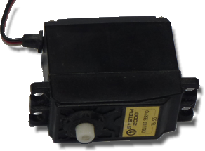
A typical R/C servo is the Futaba S148. This servo looks like a rectangular box with a motor shaft coming out of one end and a connector with three wires out of the other end. A typical servo is shown in Image 1. Attached to the motor shaft is usually (but not always) a “control horn”. This is a plastic piece with holes in it for attaching push rods or other mechanical linkages to the servo. The three wires are V+, Control, and Ground. R/C servos typically run on 4.8v (four NiCd batteries) but they often work with voltages between 4 and 6 volts. The control line is used to position the servo. In an R/C model, this line it attached to the radio reciever, on robots it is usually attached to the processor.
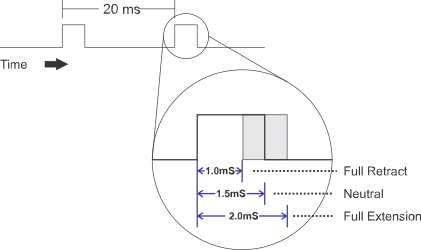
R/C Servos are controlled by sending them a “pulse” of variable width. The parameters for this pulse are that it has a minimum width, a maximum width, and a repetition rate. These values are not “standard” but there are conventions that are generally accepted. The convention is that a pulse of approximately 1500 uS (1.5 mS) is the “neutral” point for the servo. Given the rotation constraints of the servo, neutral is defined to be the position where the servo has exactly the same amount of potential rotation in the counter clockwise direction as it does in the clockwise direction. It is important to note that different R/C servos will have different constraints on their rotation but they all have a neutral position, and that position is always around 1500 uS.
These servos are “active” devices, meaning that when commanded to move they will actively hold their position. Thus, if a servo is commanded to the neutral position and an external force is present to push against the servo (presumably through the mechanical linkage) the servo will actively resist being moved out of that position. The maximum amount of force the servo can exert is the torque rating of the servo. The Futaba servo is rated around 40 oz/inches or 2.5 pounds of push at 1 inch away from from the shaft of the servo motor. Servos will not hold their position forever though, the position pulse must be repeated to instruct the servo to stay in position. The maximum amount of time that can pass before the servo will stop holding its position is the command repetition rate. Typical values for the command repetition rate are 20 - 30 mS. You can repeat the pulse more often than this, but not less often. When this timeout expires and there hasn’t been another pulse the servo de-energizes the motor. In this state in can be pushed out of position and it will not return to the commanded position.
When the pulse sent to a servo is less than 1500 uS. the servo positions and holds its output shaft some number of degrees counterclockwise from the neutral point. When the pulse is wider than 1500 uS the opposite occurs. The minimal width and the maximum width of pulse that will command the servo to turn to a valid position are functions of each servo. Different brands, and even different servos of the same brand, will have different maximum and minimums. Generally the minimum pulse will be about 1000 uS wide and the maximum pulse will be 2000uS wide. However, these are just guidelines and should be checked on the servos you use. In particular if you attempt to command a servo past its maximum or minimum rotation it will use the maximum amount of current trying unsuccessfully to achieve that position.
Another parameter that varies from servo to servo is the slew rate. This is the time it takes for the servo to change from one position to another. The worst case slewing time is when the servo is holding at the minimum rotation and it is commanded to go to maximum rotation. This can take several seconds on very high torque servos. Typically it takes less than two seconds.
Servo Construction
Servos are constructed from three basic pieces, a motor, a feedback device, and a control board. In R/C servos the feedback device is typically a potentiometer (variable resistor). The motor, through a series of gears, turns the output shaft and the potentiometer simultaneously. The potentiometer is fed into the servo control circuit and when the control circuit detects that the position is correct, it stops the motor.
The typical R/C servo varies most in its internal mechanics from other servos and this is generally the difference between “good” and “lousy” servos. The servo mechanism subsystems are the motor, the gear train, the potentiometer, the electronics, and the output shaft bearing. The electronics are pretty much all the same and so not an issue. In the motor department however you can get smaller and larger motors which effect the overall size of the servo. “mini” servos are generally more expensive than “standard” servos in part for this reason.
The gears also vary from servo to servo. Inexpensive servos have plastic gears that will wear out after less than 100 hours of use. More expensive servos have metal gears which are much more durable.
The potentiometer is the feedback device and often the first thing to fail in my servos. If it gets dirty, or the contacts get oxidized, the servo will fail to work properly, sometimes by “jittering or hunting” since the feedback is inaccurate, or turning completely to one side and drawing lots of current since the servo doesn’t know where its output shaft is pointing. More expensive servos have “sealed” potentiometers, cheaper ones do not. I’ve found I can extend the life a wee bit of my pots by using some judicious application of silicone sealant around the edge. You can do this with a syringe if your careful. Be sure and not to get it on the gears though as it will cause them to bind.
The last subsystem is the output shaft bearing. Cheap servos invariably have a plastic on plastic bearing that will not take much load. Medium priced servos generally have metal on metal bearings that stand up better under extended use and expensive servos have ball bearings which work best. Many places also sell “ball bearing upgrades” for cheap servos which consist of a new top cover and ball based bearing for the output shaft. Tower Hobbies sells three “standard” servos with the part numbers TS–51, TS–55, and TS–57 whose primary difference is the bearing. (I believe the ’57 has metal gears as well as a ball bearings)
Servo Modifications
When used with robots, R/C servos can be employed as sensor pointers, leg lifters, steering wheel turners, etc. But without modification they can not be the main drive system. Since a servo is, at its heart, a DC gear motor with enough torque to move a small platform, servos are often modified to become drive motors.
Modifing a servo to be a drive motor can use one of two strategies, breaking the feedback loop, or lobotomy.
The most brutal way of modifying a servo is the full lobotomy. You open up a servo, remove the electronics, bringing out the power lines to the motor and remove the potentiometer or modify it so that it can rotate 360 degrees. What you are left with is a DC motor, a gear train, and an output shaft on which you can mount plastic pieces that can be used as wheel mounts. This gives you complete control of the mechanics, but you do have to have a motor driver circuit to drive the DC motor in the servo housing.
Breaking the feedback loop is generally the easier way to modify a servo since it takes advantage of the power switching circuit already present on the servo to turn the motor on and off. This modification involves removing/disabling the potentiometer and replacing it with a voltage divider that convinces the servo electronics that the servo is in the neutral position. (You can figure this out by using the old pot, turned to the neutral position and measuring the resistance.) Now to turn the motor clockwise you send the servo a pulse that is wider than 1500 uS and the motor turns (and never stops because there is no potentiometer to tell the servo circuit it has gone far enough). Or to turn the motor counter- clockwise you send it a pulse less than 1500 uS wide.
This latter technique is fine except that the motor driver circuit in the servo may not be able to handle driving the motor continuously. In normal operation, the motor would be driven for a moment and then idled when the servo reached its position. The intermittent nature of turning the motor on and off allows the servo to use a motor driver that is smaller than one that would be needed for 100% duty cycle operation. If this turns out to be the case, the motor electronics will eventually burn out and you’ll end up with the full lobotomy case by default.
So there you have it, nearly everything you wanted to know about servos but were afraid to ask. :-)
–Chuck McManis

